Building a Morse Code Trainer using Raspberry PI GPIO Pins, a Button & a Buzzer.
21/02/25 by Mr Shane Currie | Charles Sturt Student
This is a technical document requiring technical expertise to understand.
In todays article I build a Morse code trainer by connecting a button and a buzzer to the GPIO pins of a raspberry PI. I use python programming language for the logic of the Morse code training program that listens for short and long presses on the button, then plays a sound on the buzzer while printing the Morse code and corresponding letter in the program. I include a video demonstration and a link to the github repository of the code below.
Key challenges that I faced was making sure that I connect the speaker and the button to the Duinotech RPI GPIO Sheild without short circuiting the raspberry PI device or sending to much current to the GPIO pins. I tested the current (mA) using a Multimeter. Now I am still learning circuitry so make sure that you know what your doing if you try this project at home, you will need to understand basic circuitry. I am only working with 3.3V to 5V here and check raspberry Pi documentation to make sure that your not overloading the current on the GPIO pins.
For the speaker/buzzer I use a different Hz for the short press and long press. I believe I used 800Hz for the short press and 600HZ for the long press. This makes it more obvious to the listener while decoding, also does not overload the speaker as to much Hz can damage the speaker.
When connecting the devices to the GPIO Shield, I make use of the S pin (signal pin) for reading HIGH or LOW current. I use HIGH and LOW current readings in my python script to determine if the button is pressed. If the current is LOW, then the button has been pressed. Also the script listens for how long the current is LOW, so it can determine if the button has been pressed for a short time, or a long time. I have included a basic curcit diagram (of the button) below.
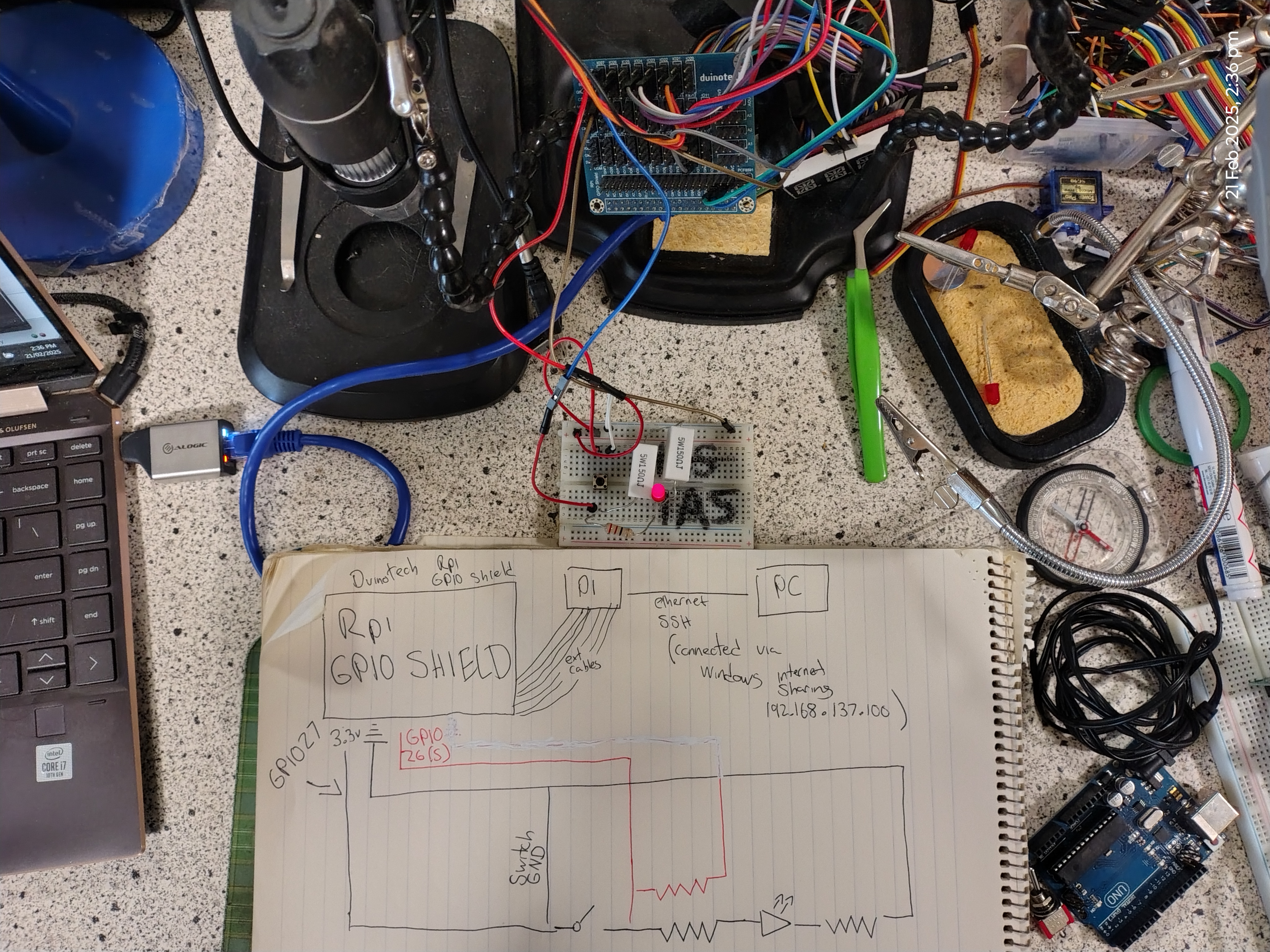
In brief laymans, to explain the circuitry. To enable the button I first power a breadboard via GPIO pin 27, this power first flows via the button, then via a resistor, then a red LED, then another resistor back to ground. On the breadboard, I include a jumper wire that connects to the signal GPIO pin 26 on the GPIO shield. This pin listens for HIGH or LOW signal . The jumper wire that I use for listening for the LOW signal is connected after the button in the circut , so if the button is pressed, it disables power flow. When the button is pressed, the jumper wire will detect a LOW signal. I make sure that this jumper wire is also properly grounded. Regarding the buzzer, this is connected to the GPIO shield and is powered via the 5v pin of GPIO 12, also the S pin of GPIO 12 and is grounded to the GND pin of GPIO 12.
Possible future upgrades I am considering is enabling this system with GenAI so you can have a conversation with a robot using Morse code. I am exploring open-source GenAI programs. The GenAI program must be lightweight and allow me to provide custom instructions to use short responses and respond in morse code. But thats a project to keep me busy for another day.